Hello everyone, I’m an Electronic Engineer and I recently received an Argon Case V2 for my Raspberry Pi 4, which I use as my media server. I have an issue with the fan. It seems other users have the same problem: the speed control isn’t linear(Argon One v2 fan speed not working). The issue is caused by the 10uF capacitor connected in parallel with the fan. The minimal duty cycle is enough to charge the capacitor and supply current for the fan to run at maximum RPM. While the capacitor eliminates switching noise, it introduces a problem with speed control. I tried removing the capacitor, but the noise (and harmonics) became unbearable.
I would like to implement (or attempt to implement) a PID control for the fan of my Raspberry Pi, purely for educational purposes. For now, I have set up the logic to turn the fan on at 100% when the Raspberry Pi exceeds a temperature of 65 degrees Celsius and to turn it off when it drops below 50 degrees Celsius, similar to a Schmitt trigger mechanism. Most of the time, the fan doesn’t turn on, which is great as the temperature stays around 52 degrees Celsius. Does anyone have any suggestions for the problem? I thought about changing the PWM frequency to a value above 20kHz to remove the PWM frequency from the audible range. I haven’t yet tested with a 10nF or 100nF capacitor, but I believe it will attenuate but not completely solve the noise issue.
Moreover, I really like the quality of the case; I am very happy with it. Once I resolve the fan issue, it will be perfect. Does anyone know the microcontroller embedded in the fan’s PCB? I tried to find information online but was unsuccessful. Perhaps increasing the operating frequency combined with choosing a better capacitor might solve the problem, I’m not sure, I will need to analyze it further.
Sorry, I hadn’t seen this information. Great! I have an appreciation for ST microcontrollers; I’ve been using them for a long time. I believe I won’t have problems creating new firmware.
I‘m currently a little bit irritated. After I searched with original name MT006C6PB I have found some websites in simple Chinese language with a ARM Cortex-M0 MT32F006/MT32F005, which seems pin compatible to the STM8S003F3. If that is true and not a fake, then it could be more complicated to make a own firmware.
If that’s the case, that is, if any Chinese microcontroller that is pin compatible with the STM8S was used, I believe the simplest thing to do would be to remove the microcontroller used (this MT32F006/MT32F005) from the PCB and replace it with the STM8S, I even have one here with me.
It’s a great project for an afternoon! I will confirm the pin compatibility and report back here, and if that is the case, I will create a repository on GitHub to provide this alternative.
With one detail, the original is actually a 32-bit ARM while the STM8S series is not ARM and is 8-bit; however, to create a PWM to control a fan, you don’t need much.
I assume too, that STM8S could be powerful enough, but I don’t know if you aware of it:
For a full replacement there are more things to do. The original does also observe the power button and communicates via short pulse to GPIO4 of the RPi, if a reboot or shutdown should initiated.
I think the power-on pin state must also implemented right, to get the case powered-on at the regular way.
Additional it must be connected to the IR receiving diode in parallel to the GPIO23 and decodes the power-on/off signal of the remote control.
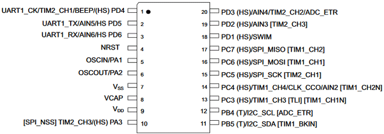
In the case of the FAN, I believe that pin 1 is the PWM control pin. This would be great, as I see from the datasheet that the STM8S has TIM2_CH1 on this pin, which gives me all the necessary hardware resources to generate a PWM.
As for the button and, especially, the IR receiver, I will have to work with external interruption. I need to check if the pins to which they are connected support external interruption.
Sorry for the silly questions, I’m new to the forum and also as a user of Argon products. Is the electrical schematic of this PCB available?
I don’t know about a public available electrical schematic of the pcb. I’m only aware of the small portion of the thread you’ve already found. There is also mentioned PIN13 at U1 in that little schematic. Therefore TIM1_CH3 or TIM1_CH1N could be used for the fan control.
It seems that one of the first milestones is to examine current pin usage. There are probably not many Argon ONE users who have the necessary equipment, skills and enthusiasm at the same time as you.
No problem! As soon as I have some spare time, I’ll get down to work. I’ll start with mapping the signals on the PCB; with that information in hand, creating the firmware for the MCU is just a matter of time. Thank you very much for the support!!