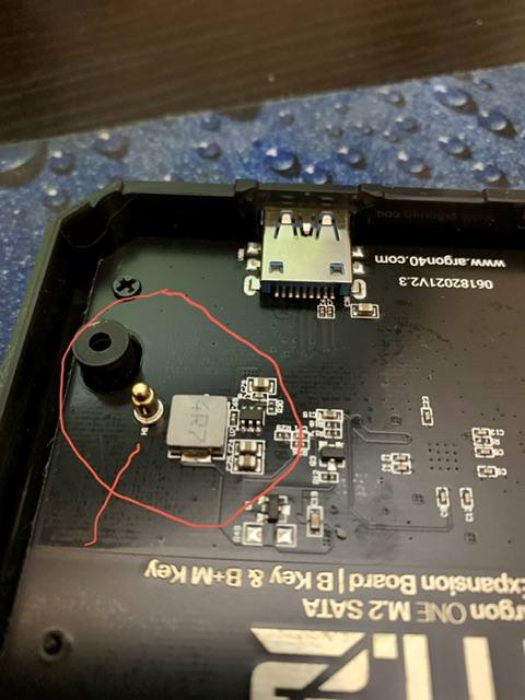
I have an extra pin that sticks out of the M.2 board on my Argon One M.2. If left alone, it would touch the bottom of the PI installed in the enclosure in what seems to be a random spot. It collapses when you push it. I put tape on my PI board to make sure it does not short out anything. I do not see it in any of the product documentation or in online photos of the base. Attached is a photo.
The total available power from the Raspberry Pi 4 USB ports is shared between all ports and limited to 1.2A (~6W).
Argon40 have addressed this by the addition of a pogo pin on the Argon ONE NVMe expansion board which contacts with a test point TP2 on the underside of the Raspberry Pi 4 PCB, which in turn is connected to Vcc (5 Volts). Thus allowing the Argon ONE NVMe board to be powered without the power limitations of the USB interface.
Judging by the photo in the first message, SATA board is provided with this POGO pin, too. However, I have experienced an SSD failure twice with my SATA SSD drives, which I presumably address to the limitation of power supply of SSD from Argon/RPi
I am also getting a very slow speed from my M.2 SATA device (about 32 MB/s), whereas from an externally attached USB3 device (i.e. NOT via the Argon M.2 unit), I get about 291 MB/s, both on the same Pi4.
Is the lack of extra power causing the slow speed? Can I improve things somehow? Thanks for any advice!
They added it, but for me, it had the unintended side effect of not allowing the Pi to boot at all. Once I covered the pin with tape, it started booting normally. I have the M2 Sata version with a teamgroup 256 m2 sata drive.
The info on that other behavior is on this thread: here
I experience the same problem. I obtained a new Argon One M.2 SATA expansion board. The board I received shows version 2.3 and it includes the pogo pin. After installing it as directed, my Raspberry Pi would no longer boot. Covering the test point TP2 with electrical tape solved the problem. However, I think covering the test point TP2 with tape should not be the solution. It is my understanding the purpose for the pogo pin is to provide +5 Vcc to the M.2 enclosure from the Pi power supply and not from the USB ports. The reason is because the power from the USB ports is shared between all ports and is limited to 1.2A (~6W). This could cause some SDD drives that require more power to not boot. Especially if all USB ports are in use. It would be good to know if the manufacturer is aware of this issue and if they have found any workarounds or solutions for this problem.
Hi there,
I think one should actually de-solder the Vbus pin of the USB connection and let the power be provided via the pogo pin. Because large SSDs like the 4TB drive I am planning to use may draw more than the 1.2 amps the Pi4 provides over USB.
So, I am in the opposite situation here: version 2.2 m.2 SATA expansion board without pogo pin and the big drive doesn’t work reliably. If the SSD is plugged into a powered USB hub, everything works like a charm.
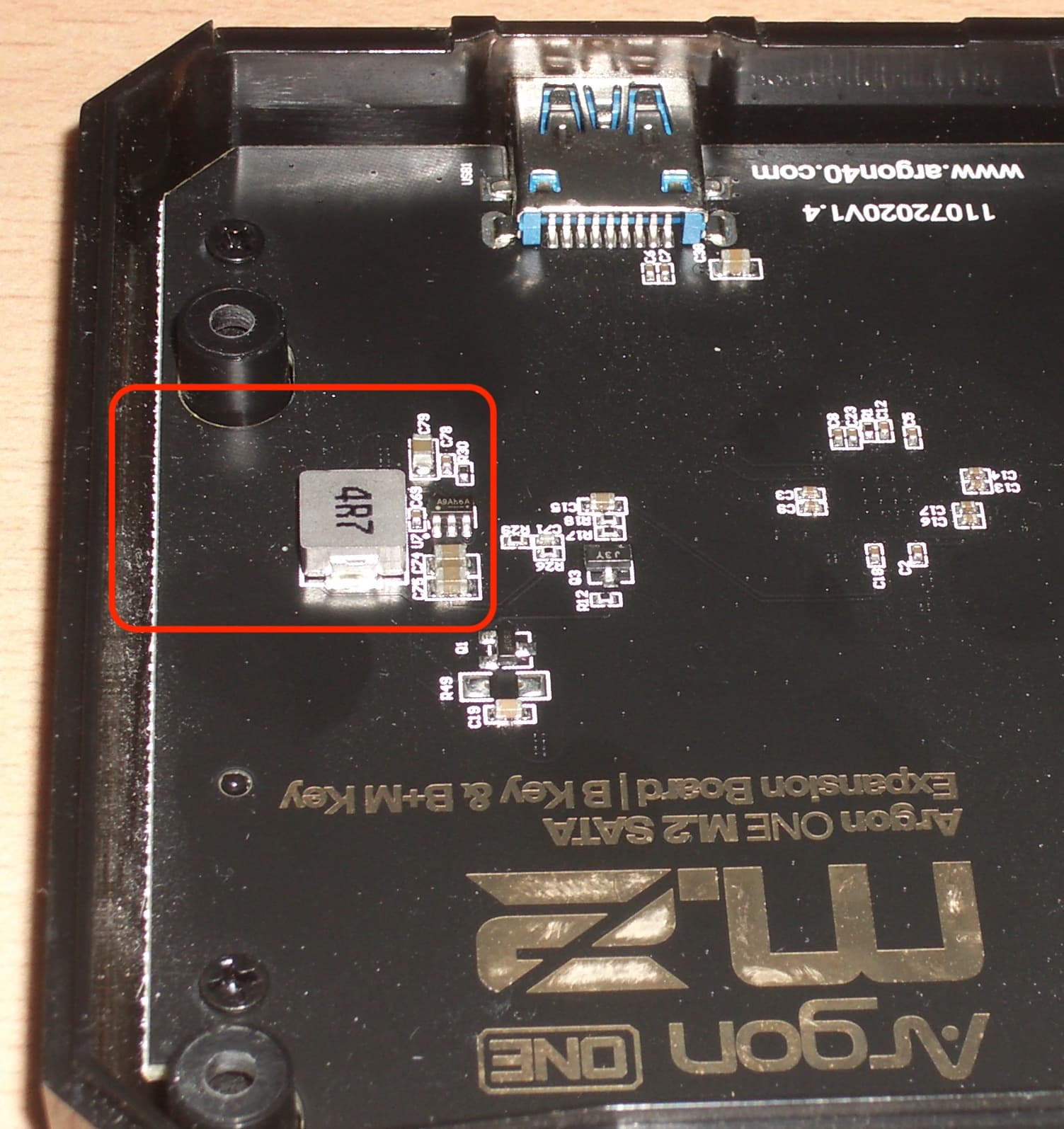
So my question would be, if anyone knows if there is a point on the version 2.2 m.2 SATA board I can solder a jumper wire to establish a connection to the test point 2 without pogo pin? Would one of the sides of the coil be suitable? I suspect the coil is part of an LC filter that’s supposed to filter the 5 V coming in via USB.